Initialization
Technology
For this project, I will be using the Rust programming language with the wgpu library for communicating with the GPU and shader compilation. wgpu is an implementation of the WebGPU (different from WebGL) standard, which uses OpenGL, DirectX, Vulkan or Metal as a backend when running natively, and WebGL when running in a browser. This is because most browsers don’t support WebGPU itself yet. It also uses the WebGPU Shading Language (WGSL) for its shader code, but is able to cross compile GLSL as well. I will be using WGSL despite its immaturity and wgpu’s naga shader compiler not fully implementing the specification, simply to force myself to implement things myself instead of copy pasting code.
Browser? Did I read that right?
Yes! Rust compiles to WebAssembly, so if I have time, I may be able to provide an interactive demo that you don’t need to download and install yourself once the project is complete!
First steps
I began by going through the learn wgpu tutorial to get some understanding of how the library works. That was quite fun, but I did not like how poorly structured the code ended up. Over 600 lines in the main file!
I then deleted all of the code related to things I won’t use, such as obj model loading and vertex/fragment rendering. Some of it I’m still unsure if I might need, or be able to reuse, such as the depth buffer, so they remain for now.
I replaced the deleted code with a compute shader in which I will be doing the rendering, and the things needed to get it to output an image. I can’t use a fragment shader for this, as those require each pixel to have the same flow through the program, meaning I can’t have if statements and other control flow operations.
To verify that it worked, and that I had an understanding of how to know what pixel I’m drawing, I had it draw a mandelbrot set:
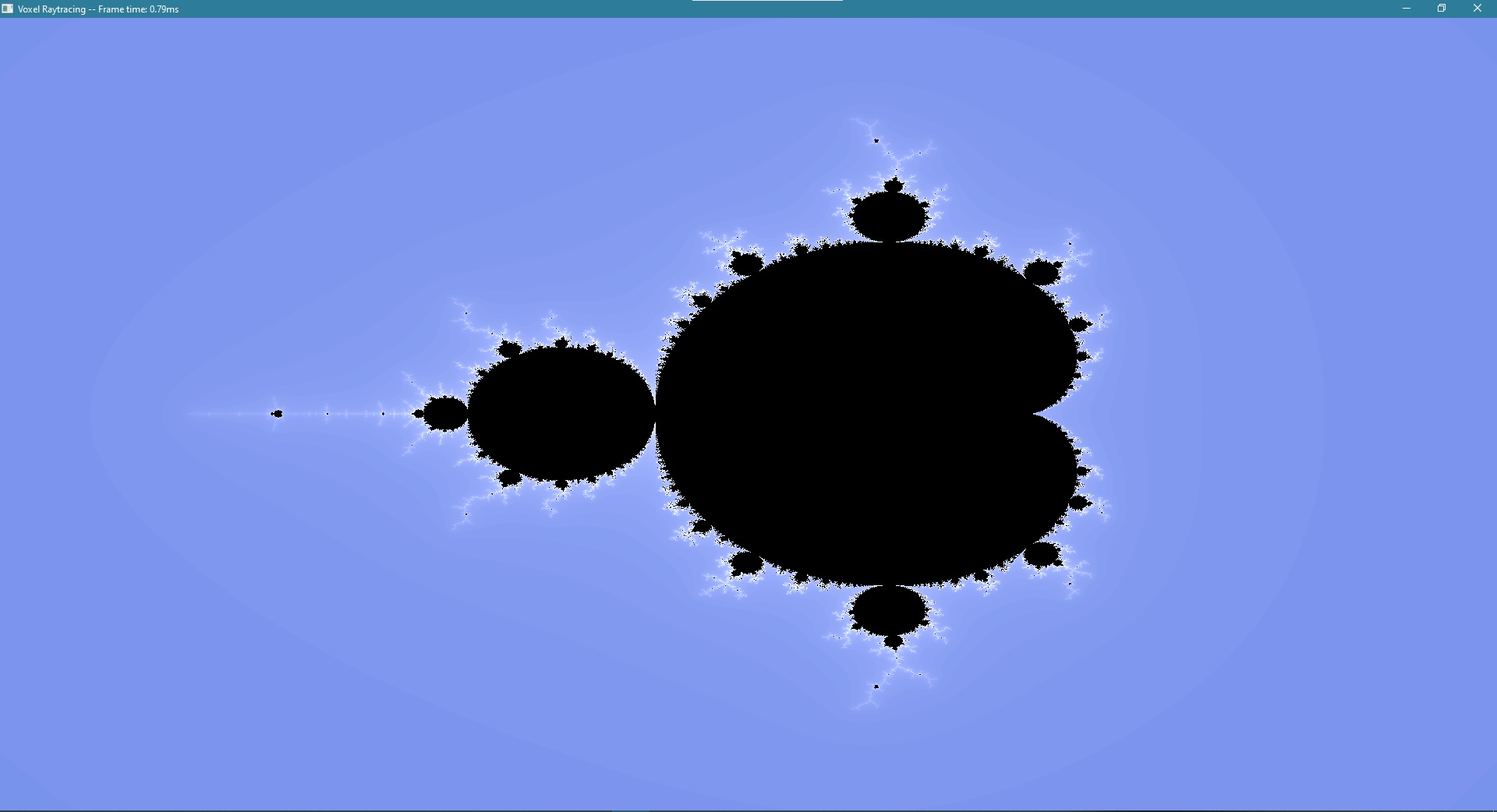
An issue I didn’t realize when choosing this as the test is that it’s symmetric across the x-axis, so the whole time I was drawing everything upside down! I had a hard time figuring this out when I actually found the problem, but in the end I solved it by changing the texture coordinates I had hardcoded into the shader I use to present the image to the screen.
As for how I found the problem, it happened when I was doing the next few steps.
Actually 3D
The mandelbrot image was a step back from the 3D scene I had at the end of the wgpu tutorial, so I had to get some 3D aspects back. As I didn’t like how the camera from the tutorial worked, I restructured the rust side of that, and replaced the view * projection matrix it had been sending to the gpu with the inverses of both of these matrices, as it’s the inverses that are needed for calculating the rays I want to trace.
I know this is kind of the wrong order to do things, but I wanted to have a pretty skybox in the background, so I looked at some examples of how to do that and got it implemented. Then I added a box to the shader that I intend to use as a bounding box for the voxel scene, but for now it’s empty, only used to verify that things work. I made functions for getting the intersection points with the box and the normal of the box at the intersection. Then I made the color of the pixel correspond to the normal of the box where it hit, or the color of the skybox if it misses the box.

As stated before, this was initially all upside down, and the camera controls were inverted and very difficult to maneuver. After some debugging of UV coordinates, I figured out that (U+,V+) corresponding to (right, down), which I was using in the screen shader, didn’t match with whatever positions the compute shader was drawing to, so I ended up changing them to what they would be in OpenGL, where (U+,V+) corresponds to (right, up). And with that, I got the scenery above!
In the next post, I will start actually tracing rays through scenes.